What are the Load-Sensing Control?
Load-sensing is a type of variable pump control widely utilized in hydraulic systems to regulate open circuits. Despite its significance in hydraulic control, load-sensing remains not fully comprehended by many operators. As a result, it is imperative for maintenance technicians to possess a comprehensive understanding of equipment operation.
Also known as load-induced pressure sensing, load-sensing entails detecting the downstream pressure from an orifice and adjusting the pump's flow accordingly to maintain a constant pressure drop across the orifice. This orifice typically takes the form of a directional control valve with proportional flow characteristics, a needle valve, or a fixed orifice, depending on the specific application.
One of the primary benefits of employing a load-sensing controlled variable pump is its power-saving capability. By restricting power loss due to heat to a minimal pressure drop across the metering orifice, which remains constant across the system's operating pressure range.
Efficiencies achieved by utilizing a load-sensing controlled variable pump include:
- Elimination of excess flow passing over the system relief valve in fixed displacement pumps, which converts to heat, especially if the load-induced pressure is lower than the set relief pressure.
- Reduced power loss in systems equipped with pressure-compensated variable pumps, where a portion of the available flow is required at pressures below the maximum system pressure, resulting in power loss due to significant pressure drop across the metering orifice as it regulates pump flow at the maximum pressure setting.
The load-sensing circuit configuration typically comprises two main components:
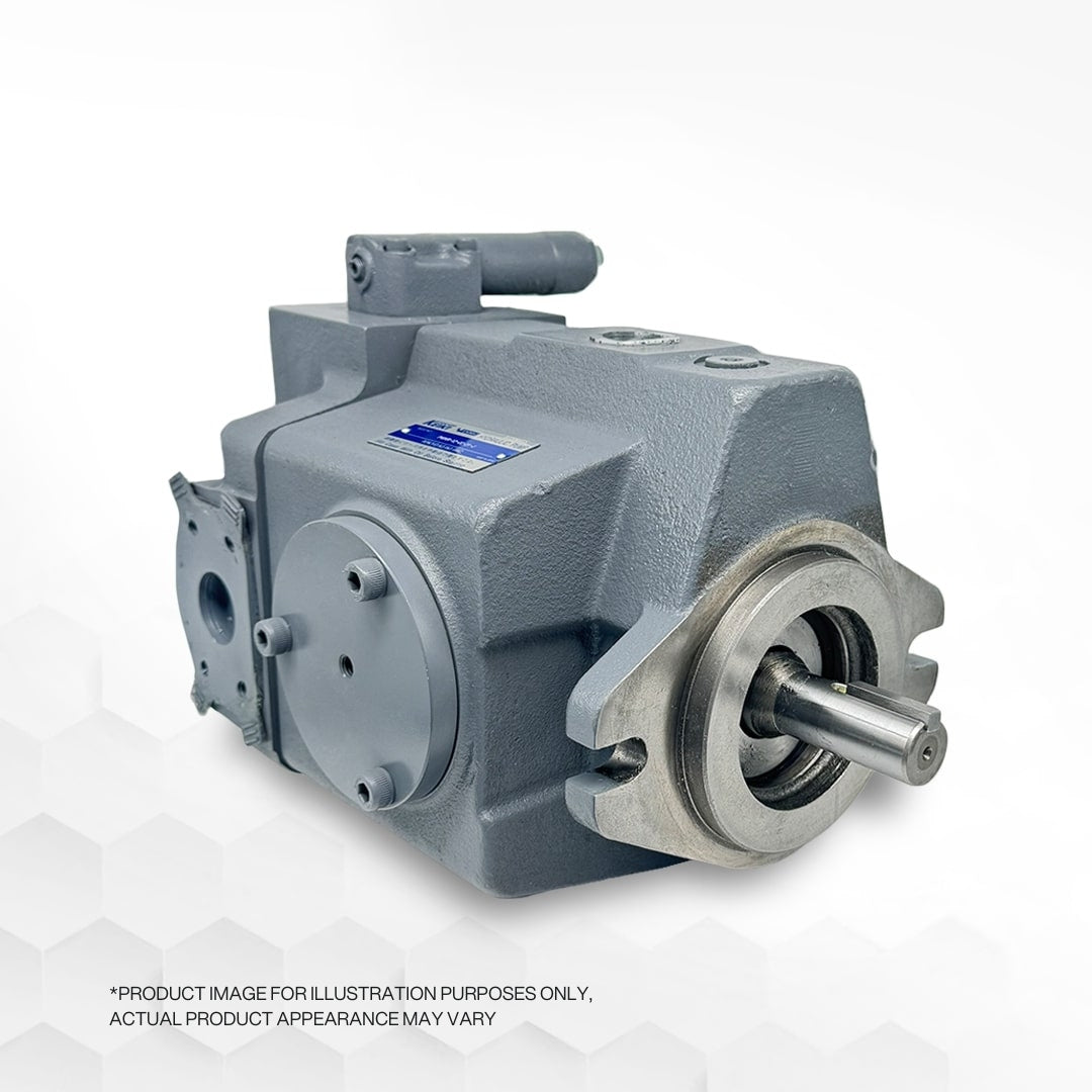
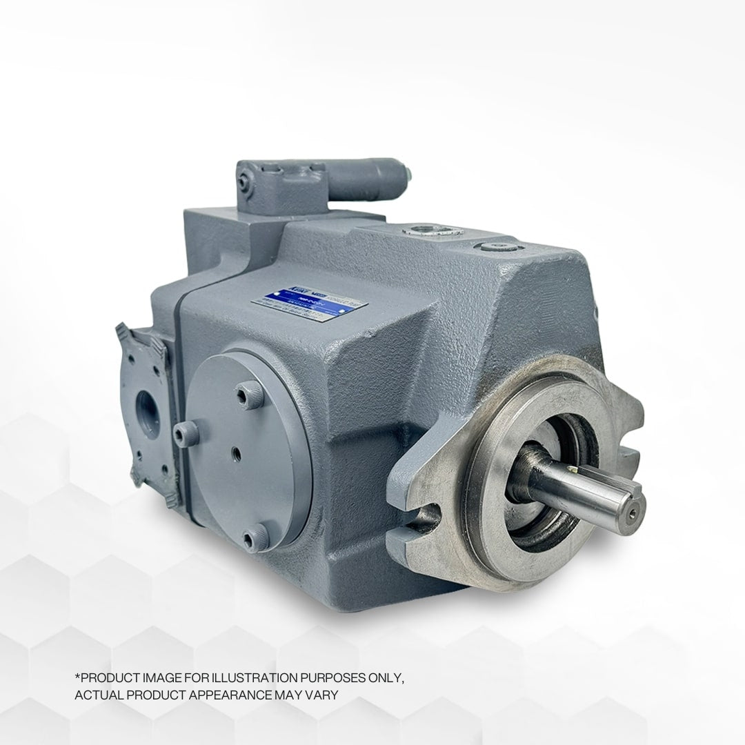
- Variable displacement pump - typically an axial-piston design - equipped with a load-sensing controller.
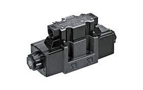
- Directional control valve with an integral load-signal gallery.
When the load-sensing pump and directional control valve collaborate, envision a winch driven through a manually actuated valve. The operator instructs the winch by moving the spool in the directional valve to a certain percentage of its stroke, causing the winch drum to turn at a specific rpm. The load-signal gallery, connected to the load-signal port (X) on the pump controller, ensures that the actuator with the highest load pressure is sensed and fed back to the pump control through a series of shuttle valves in the directional control valve.
As the load on the winch increases, the load-induced pressure downstream of the orifice (directional valve) strengthens, leading to a decrease in pressure drop across the orifice, subsequently reducing flow across the orifice and slowing down the winch.
To maintain a constant pressure drop across the orifice (directional valve), the load-sensing controller responds to increased load pressure by slightly increasing pump displacement (flow), resulting in an equal and consistent increase in pressure upstream of the orifice. Consequently, flow and winch speed remain constant.
Typically, the pressure drop or delta p maintained across the orifice (directional valve) ranges from 10 to 30 bar (145 to 435 PSI). When all spools are in the neutral position, the load-signal port is vented to the tank, and the pump maintains standby pressure equal to or slightly higher than the load-sensing control's delta p setting.
Some high-end load-sensing directional control valves feature a pressure compensator at the inlet to each valve section. The action of the section pressure compensator, combined with the orifice opening selected by the spool, ensures a constant flow rate unaffected by pressure variations caused by simultaneous operation of multiple functions. This is sometimes referred to as "sensitive load-sensing."
In conclusion, load-sensing control offers energy efficiency by supplying the flow demanded solely by the actuators, leading to lower oil oxidation rates, extended fluid life, and improved actuator control. Additionally, it provides a constant flow independent of pump shaft speed variations.
