Understanding Heat and Its Impact on Hydraulic Systems
WHAT IS HEAT?
Heat in Hydraulic Applications is being generated anytime fluid flows from high pressure to a lower pressure, without producing mechanical work output.
CAUSES OF HEAT GENERATION
- Flow restriction or throttling - The use of flow controls, proportional, reducing, relief, reducing/relieving, counterbalance, and servo valves all create a pressure drop in order to do their job.
- Excessive flow Velocities - Incorrect sizing of fluid conductors can cause the generation of heat. For example, with ½ inch OD pipe, a flow rate of 10 GPM generates heat at the rate of about 25 BTU/FT-HR. Doubling the flow rate to 20 GPM increases heat generation 8 times to about 200 BTU/FT-HR. Here are some rules of thumb when sizing hydraulic conductor velocities:
- Pump suction lines should be sized for 2 - 4 ft/sec
- Return lines should be sized for 10 - 15 ft/sec
- Medium pressure lines (500 - 2000 PSI) should be sized for 10 - 15 ft/sec
- High-pressure lines (3000-5000 PSI) should be sized for 20-30 ft/sec
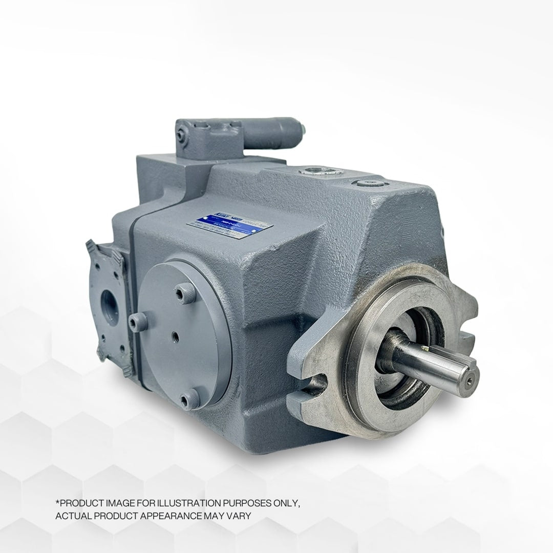
- Slippage in pumps - Slippage can happen depending on the type of pump. The leakage flow from the high-pressure outlet back through the pump to the low-pressure inlet in the case of a fixed displacement pump. Whilst in a pressure compensated pump, the flow is forced out through the case drain. Thus, slippage increases because of the pump's internal leakage.
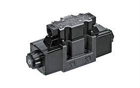
- Internal leakage in valves - This internal leak is created by wear of the valves causing the high-pressure oil to leak to a low-pressure port developing heat.
- Gas-filled accumulators - Vibrating accumulators may develop high pressures on the gas side. High pressure is equal to an increase of oil temperature and hot spots would be the hydraulic system's new problem.
- Non-regenerative release of potential energy - Potential energy is stored in the load when a load is lifted hydraulically. Once released, can usually involve non-regenerative throttling, which generates heat.
EFFECTS OF HEAT ON THE SYSTEM
Oil temperatures should be maintained at 120°F for optimum performance, and should never be allowed to exceed 150°F. This must be monitored for heat has many damaging effects on the hydraulic system components. To name a few:
- Breakdown of the oil. At high temperatures, oxidation of the oil is accelerated that shortens the fluid's useful life by producing acids and sludge, which corrode metal parts. This change or breakdown of the hydraulic media can be extremely detrimental to hydraulic components, especially pumping equipment.
- Lowering of the oil's viscosity and its ability to lubricate the moving parts of the pump and related hydraulic equipment effectively.
USEFUL HEAT CALCULATIONS
- HP = horsepower
- GPM = gallons per minute
- PSI = pounds per square inch
- HP = GPM x PSI / 1714
- 1HP = 2545 x BTU/hr
- HP x 746 = KW
- KW x 3413 = BTU/hr
- KW x 1341 = HP
RECOMMENDATIONS TO REDUCE HEAT GENERATION
- Empty the pump during intervals when pressure is not required - Just add a solenoid vented relief valve on fixed displacement pumps and a solenoid vented control on pressure-compensated pumps to remove the high-pressure component.
- Use the largest reservoir that is realistic for your application - This will gain the most surface area or cooling capacity from the reservoir.
- Set the main system relief to the lowest acceptable and safest value - This setting is usually 200 -250 PSI above the maximum pressure needed in the system to do the work.
- Place the tank in a place that has the greatest amount of airflow - By doing so you greatly reduce the tank's capacity to diffuse heat and in some applications can cause the system to prematurely overheat.
- Establishing or designing heat exchangers into the system will help remove excess heat.
- Heat exchangers can be used to remove the excess heat in a hydraulic system but has many variables that need to be taken into account during implementation. Here are the following:
- Simple circuit with minimal valves - 25%
- Simple circuit with cylinders - 28%
- Simple circuit with fluid motors - 31%
- Hydrostatic transmissions - 35-40%
- Servo based systems - 60-75%
- Low-pressure fluid transfer systems - 15%
Get the product of the input horsepower (motor hp) and the percentage listed above that best describes the system parameters. For example, if your system is a simple circuit with fluid motors and has an electrical motor input horsepower of 30hp: 30hp X 0.31 = 9.3hp
The tank needs to evaporate at least 9.3 horsepower or the system will overheat. Another rule to keep in mind is if your system pressure is above 1000 PSI and your tank is sized for 3 times or less pump output you WILL need a heat exchanger.
CONCLUSION
The hydraulic system has indeed a lot of thermal characteristics to be considered to extend the service life of its equipment. As briefly discussed in this article, you may be able to make educated decisions when working with an existing system or new design in order to combat heat generation. Consequently, you should consult your local fluid power professional when in doubt about any possible outcomes.
