How to Properly Set Relief Valves
Correctly setting up standalone relief valves is a straightforward process. Once a relief valve is added to a circuit, it should be adjusted to the lowest pressure setting, with the tank port directly connected to the reservoir and the pressure port linked to the pressure line. This precaution ensures the prevention of unforeseen conditions when hydraulic power is applied to the circuit. After the relief valve has been appropriately installed and set to its lowest level, the fluid power can be turned on. It is important to note that at this lowest pressure setting, flow may rush through the relief valve, causing some noise.
To set system relief valves in circuits with fixed displacement pumps, the aforementioned procedure is frequently employed. However, the process becomes slightly more complex when dealing with a relief valve used in a pressure-compensated pump circuit. The relief valve should be installed as previously described, with the tank port directly connected to the reservoir and the pressure port attached to the pressure line. Ensuring that the relief valve is set to withstand the lowest pressure is vital in preventing unexpected conditions when hydraulic power is supplied to the circuit. Once the new relief valve and pump compensator have been correctly installed, they should both be set to their minimal settings.
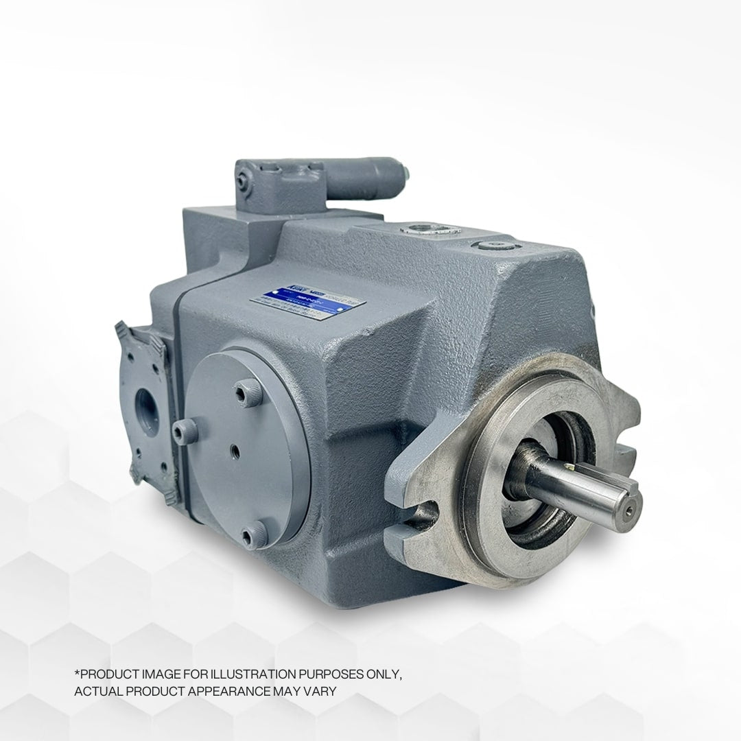
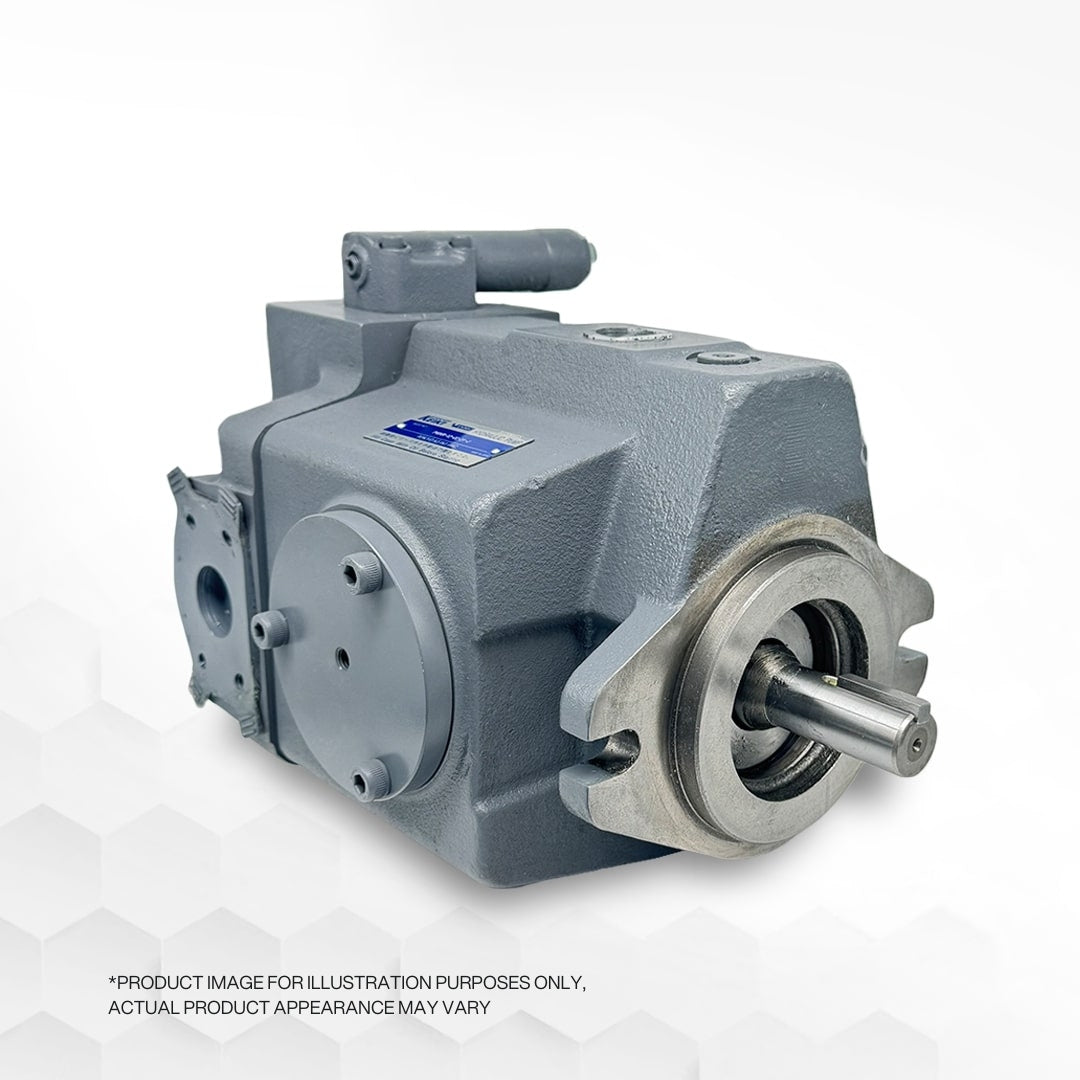
Subsequently, the hydraulic pump should be started, and the system relief valve should be gradually turned almost all the way up. At the same time, the pump pressure compensator's setting should be increased by approximately 200 PSI above the intended system pressure. While doing so, observe the pressure gauge connected to the new relief valve's circuit. When the pressure on the gauge falls below the pump compensator's setting, begin lowering the system relief valve's setting. Lock the system relief valve at the setting that keeps the pressure 200 PSI higher than the required level.
Finally, adjust the pump pressure compensator setting to the desired system pressure. To prevent conflicts between the two pressure settings, the system pressure relief valve must be set 200 PSI higher than the pump pressure compensator setting. As a result, the system will behave as if it has a fixed displacement. However, it is important to note that this configuration may cause the pump to generate louder noises, and the hydraulic fluid may produce more heat.
Cascade Industrial Services Corp. specializes in providing hydraulic system design, products, and solutions for enhancing machine performance in both mobile and industrial circuits. Their team of Certified Fluid Power Specialists assists in selecting the most effective and economical systems and components.


